On Rendering the Sky, Sunsets, and Planets - The Blog of Maxime Heckel
There’s this photo that’s been sitting on my inspiration board for a while, of the space shuttle Endeavour, suspended in space in low Earth orbit at sunset. It shows Earth’s upper atmosphere as a backdrop, featuring beautiful, colorful layers ranging from dark orange to blue before fading away into the deep black of space. Not only is that gradient of color aesthetically pleasing, but the phenomenon behind those colors, atmospheric scattering, is even more of an interesting topic once you start looking into how it works and how to reproduce it.
有一张照片,我一直把它保存在我的灵感板上。照片中的是“奋进号”航天飞机,在日落时分悬浮在近地轨道上。地球的高层大气构成了这张照片的背景:从深橙色到蓝色,各种美丽的色彩层次清晰可见,随后又逐渐融入了宇宙的黑暗之中。这种色彩的渐变不仅美观,而且,导致这种色彩现象的大气散射现象本身,也是一个非常有趣的研究主题——只要开始探究其原理并尝试再现这一现象,就会发现其中蕴含的奥秘。
![[shuttle.webp|Shuttle Silhouette https://www.nasa.gov/image-article/shuttle-silhouette-2/]]
Shuttle Silhouette https://www.nasa.gov/image-article/shuttle-silhouette-2/ 航天飞机剪影 https://www.nasa.gov/image-article/shuttle-silhouette-2/
I wanted to build my own version of this effect with shaders, rendering the sky’s distinctive blue color and realistic sunsets and sunrises directly in the browser. The goal was to get as close as I could to that photo, while also moving toward the kind of atmospheric rendering often seen in games and other shader-based media.
我想要利用着色器来打造出类似的效果:在浏览器中直接渲染出天空的蓝色、以及逼真的日落和日出景象。我的目标是尽可能地接近那张照片的效果,同时也要呈现出那种常见于游戏和其他基于着色器的媒体中的氛围渲染效果。
Here’s a compilation of what came out of this month-long journey, all running in real time:
以下是这段为期一个月的旅程中所有实时发生的事情的汇总:
I didn’t originally plan on writing about this subject, but the enthusiasm around the recent Artemis II mission, combined with my own interest in all things space, made it feel worth exploring in depth. It also felt like the perfect opportunity to build an interactive experience that could make the topic more accessible. In this write-up, we’ll see how to implement an atmospheric scattering shader post-processing effect step-by-step, starting with the implementation of the different building blocks (raymarching, Rayleigh and Mie scattering, as well as ozone absorption) to render a realistic sky dome, and then adapt the result to render it as an atmospheric shell around a planet. Finally, we’ll look into Sebastian Hillaire’s LUT-based approach for a more performant result, or at least my attempt at implementing it, as this was very much the stepping outside of my comfort zone phase for this project.
我最初并不打算撰写关于这个主题的文章。但由于最近“阿耳忒弥斯 2 号”任务引发的热议,再加上我个人对太空领域的浓厚兴趣,我觉得有必要深入探讨这个话题。同时,这也是一次创造互动式体验的绝佳机会,从而让这个主题更容易被人们理解。在这篇文章中,我们将一步步介绍如何实现大气散射着色器后期处理效果。首先,我们会实现各个必要的构建模块:raymarching、瑞利散射和米氏散射,以及臭氧吸收,从而渲染出逼真的天穹。接着,我们会把这一技术应用到行星周围的大气壳渲染上。最后,我们还会探讨 Sebastian Hillaire 提出的基于 LUT 的方法,以获得性能更好的结果。当然,这只是我的尝试而已,因为这确实超出了我的舒适区。
How to Render a Sky如何渲染天空效果
You may have, at some point or another, tried to slap a blue gradient background behind some of your work in an attempt to give it a more “atmospheric” look and call it a day, but quickly noticed doing so never feels quite right 1.
你可能在某个时候尝试过,为自己的作品添加蓝色的渐变背景,希望能让作品看起来更“有氛围感”。但很快你就会发现,这样做其实并不理想 1 。
For a more true to life implementation, we must treat the sky and its color as the result of light interacting with air and its constituents, while taking into account several variables, such the altitude of the observer, the amount of dust, the time of day, etc, all of that in a volume.
为了更真实地再现这一现象,我们必须将天空及其颜色视为光线与空气及其中各种成分相互作用的结果。同时,还需要考虑多种因素,比如观察者所处的海拔高度、空气中的尘埃含量、一天中的不同时间等等。所有这些因素都需在特定的空间范围内加以考虑。
With that established, our goal for this first part is to use this as guiding principle to lay the foundation for our atmosphere shader, and get to a result that feels almost indistinguishable from a real sky, at any time of the day.
既然如此,本阶段的目标就是以这一原则作为指导,为大气着色器的开发奠定基础。最终要实现的效果是:无论是一天的中的什么时间,渲染出来的大气效果都应与真实的天空几乎无法区分。
Sampling Atmospheric Density大气密度采样
Much like how we’d approach volumetric clouds or volumetric light, one easy way to sample the atmosphere is through raymarching. We can cast rays from the camera’s position into the scene and step through the transparent medium to answer the two following questions:
就像处理体积云或体积光时的方法一样,一种简单的采样大气的方法就是使用 raymarching。我们可以从相机的位置向场景中发射射线,然后沿透明介质逐步采样,从而回答以下两个问题:
- How much light survives traveling through the atmosphere? This is the transmittance term.
有多少光线能够穿透大气层呢?这就是所谓的“透射率”。 - How much light is redirected toward the camera at each sample? Also known as scattering.
在每个样本处,有多少光线被重新导向了相机?这一现象也被称为“散射”。
To answer the first one, we need to accumulate the atmospheric density encountered along the ray to obtain what is known as the optical depth. We will model this using the Rayleigh density function, which tells us how much “air” there is at a given altitude h. This is important to take into account that the atmosphere gets thinner as altitude increases.
要回答第一个问题,我们需要累计光线传播路径上所遇到的大气密度,从而得到所谓的“光学深度”。我们将使用瑞利密度函数来对这一过程进行建模。该函数能够告诉我们,在特定高度处有多少“空气”。需要记住的是,随着高度的增加,大气密度会逐渐减小。
Sampling Rayleigh density and accumulating optical depth
对瑞利密度进行采样并计算光学厚度
const float RAYLEIGH_SCALE_HEIGHT = 8.0; // km
const float ATMOSPHERE_HEIGHT = 100.0; // km - Karman line
const float VIEW_DISTANCE = 200.0; // km
const int PRIMARY_STEPS = 24;
const vec3 SUN_DIRECTION = normalize(vec3(0.0, 1.0, 1.0));

float rayleighDensity(float h) {
  return exp(-max(h, 0.0) / RAYLEIGH_SCALE_HEIGHT);
}

void main() {
  vec2 p = vUv * 2.0 - 1.0;

  vec3 color = vec3(0.0);
  vec3 viewDir = normalize(vec3(p.x, p.y, 1.0));
  vec3 skyDir = normalize(vec3(viewDir.x, max(viewDir.y, 0.0), viewDir.z));

  float stepSize = VIEW_DISTANCE / float(PRIMARY_STEPS);
  float viewOpticalDepth = 0.0;

  for (int i = 0; i < PRIMARY_STEPS; i++) {
    float t = (float(i) + 0.5) * stepSize;
    float h = t * skyDir.y;

    if (h < 0.0) break;
    if (h > ATMOSPHERE_HEIGHT) break;

    float dR = rayleighDensity(h);
    viewOpticalDepth += dR * stepSize;

    // ...
  }

  //...

  color = ACESFilm(color);

  fragColor = vec4(color, 1.0);
}
Then, from the optical depth, we can compute the transmittance T at a given point along the ray: the fraction of light that survives while traveling through the atmosphere.
然后,根据光学深度,我们可以计算出光线在传播过程中经过某一点的透射率——也就是光线在穿过大气层时仍然保留下来的比例。
T=1.0means that there is no loss of light.
T=1.0表示没有光线损失。T=0.0means that the light is totally extinguished.
T=0.0表示光线已经完全衰减。
If you’ve read my article on volumetric clouds 2, we’re using a formula that may look familiar for this: Beer’s Law:
如果您读过我关于体积云的文章 2 ,那么您应该对这里所使用的公式并不陌生:比尔定律。
Computing transmittance 计算透射率
//...

float dR = rayleighDensity(h);
viewOpticalDepth += dR * stepSize;

vec3 transmittance = exp(-rayleighBeta * viewOpticalDepth);
scattering += dR * transmittance * stepSize;

//...
With this in place, we can now describe how light is attenuated as it travels through the atmosphere. However, density and transmittance only tell us how much light is available to scatter, not how that light is distributed toward the viewer. For that, we need to account for the angle between the incoming sunlight and the view ray, which is what the Rayleigh phase function models.
有了这些知识,我们现在就可以描述光在穿过大气层时是如何被衰减的。不过,密度和透射率只能告诉我们有多少光可以被散射,而无法说明这些光是如何向观察者方向传播的。为此,我们需要考虑入射阳光与观察方向之间的夹角,而这正是瑞利相位函数所用来描述的。
Rayleigh phase function 瑞利相位函数
//...

// We consider the sun constant at its zenith here
const vec3 SUN_DIRECTION = normalize(vec3(0.0, 1.0, 1.0));

float rayleighPhase(float mu) {
  return 3.0 / (16.0 * PI) * (1.0 + mu * mu);
}

//...
void main() {
  //...
  float phase = rayleighPhase(dot(skyDir, SUN_DIRECTION));

  // Raymarching loop

  scattering *= SUN_INTENSITY * phase * rayleighBeta;

  float horizon = smoothstep(-0.12, 0.05, skyDir.y);
  vec3 color = mix(SPACE_COLOR, scattering, horizon);
  color = ACESFilm(color);

  fragColor = vec4(color, 1.0);
}
Putting all this together, we can have a somewhat accurate representation of how much scattered light accumulates along a given ray at any given altitude. The widget below represents the process we just described, showing you:
把这些部分组合起来,我们就能近似计算:在任意高度上,沿着某条特定射线路径,会有多少散射光被累积下来。下方的图表展示了我们刚才所描述的过程。
- The sample steps along a single ray
样本沿着单一光线移动的步骤/样本在单一光线路径上的移动过程 - The resulting pixel color obtained from this process (an approximation)
通过这一过程得到的像素颜色值(仅为近似值)
20
3.5 km 3.5 公里
As you can see, we’re accumulating shades of blue at lower altitude! This is mostly due to the Rayleigh scattering coefficient’s value:
如您所见,我们在较低海拔地区观察到了越来越多的蓝色色调!这主要得益于瑞利散射系数的作用。
- Red scatters very little 红色几乎不会扩散。
- Green a bit more 绿色散射稍多一些
- Blue the most 蓝色散射最多
Since shorter wavelengths scatter more strongly, more blue light is redirected toward the viewer, thus resulting in the sky appearing blue during daytime.
由于波长较短的光更容易发生散射,因此更多的蓝光会被重新定向到观察者的方向。这就是为什么在白天,天空会呈现蓝色的原因。
If we expand this idea into a full-on fragment shader, going from a single ray to one ray per pixel, we can render a realistic sky, as demonstrated below:
如果我们把这个想法进一步应用到完整的片段着色器中,也就是让每个像素都对应一条光线,那么我们就能渲染出逼真的天空效果,如下图所示:
Uniforms 参数
20.00
2.00
This raymarching process yields a beautiful blue sky, with a lighter white haze towards the horizon as rays travel through more atmosphere there, and deeper, darker blue colors as the altitude increases and the atmosphere gets thinner.
通过这种 raymarching 处理,我们可以得到美丽的蓝天效果:随着光线穿过更多的大气层,地平线处呈现出更浅的白色雾霭;而随着高度的增加,大气层变薄,颜色则变为更深的蓝色。
Mie Scattering and Ozone米氏散射与臭氧
While Rayleigh scattering alone yields a decent result, there are still additional atmospheric effects that we can take into account to make our sky rendering closer to reality:
虽然仅利用瑞利散射就能得到相当不错的效果,但我们还可以考虑其他大气效应,从而让天空的渲染效果更接近真实情况:
- Mie Scattering, which describes the interaction of light with larger particles in the atmosphere, like dust or aerosols. It has a density function to account for the amount of material in the medium, as well as a phase function, which, like its Rayleigh counterpart, describes how the light gets redistributed in different directions.
米氏散射现象描述了光与大气中较大颗粒的相互作用,这些颗粒包括灰尘和气溶胶等。该现象包含一个密度函数,用于描述介质中物质的分布情况;同时还有一个相位函数,其作用与瑞利散射类似,即描述光是如何向不同方向传播的。 - Ozone absorption, which models how ozone absorbs part of the light passing through the upper atmosphere. This one does not scatter light; it only removes some wavelengths along the path. Its main contribution is to shift and deepen the sky’s color, especially near the horizon and during sunsets or twilight.
臭氧吸收作用指的是臭氧如何吸收穿过高层大气的一部分光线。这一过程并不涉及光线的散射,而是直接滤除了特定波长的光线。其主要作用是使天空的颜色发生变化,让天空看起来更暗淡,这一效果在地平线附近、日落或黄昏时尤为明显。
The first one can be modeled with the following two functions:
第一个可以用以下两个函数来建模:
Mie density and phase function
米氏密度与相函数
float miePhase(float mu) {
  float gg = MIE_G * MIE_G;
  float num = 3.0 * (1.0 - gg) * (1.0 + mu * mu);
  float den = 8.0 * PI * (2.0 + gg) * pow(max(1.0 + gg - 2.0 * MIE_G * mu, 1e-4), 1.5);
  return num / den;
}

float mieDensity(float h) {
  return exp(-max(h, 0.0) / MIE_SCALE_HEIGHT);
}
To get the updated scattering term that takes Mie scattering and Ozone into account, we simply add it to the current implementation of our sky shader on top of the Rayleigh density and phase function:
为了得到同时考虑了米氏散射和臭氧效应的更新后的散射公式,我们只需将其添加到当前的天空着色器的实现中,即叠加在瑞利散射的密度和相位函数之上即可。
float viewODR = 0.0;
float viewODM = 0.0;
float viewODO = 0.0;

vec3 sumR = vec3(0.0);
vec3 sumM = vec3(0.0);
vec3 sumO = vec3(0.0);

for (int i = 0; i < PRIMARY_STEPS; i++) {
  float t = (float(i) + 0.5) * stepSize;
  float h = uObserverAltitude + t * skyDir.y;

  if (h < 0.0) break;
  if (h > ATMOSPHERE_HEIGHT) break;

  float dR = rayleighDensity(h);
  float dM = mieDensity(h);
  float dO = ozoneDensity(h);

  viewODR += dR * stepSize;
  viewODM += dM * stepSize;
  viewODO += dO * stepSize;

  vec3 tau = BETA_R * viewODR
    + BETA_M_EXT * viewODM
    + BETA_OZONE_ABS * viewODO;
  vec3 transmittance = exp(-tau);

  sumR += dR * transmittance * stepSize;
  sumM += dM * transmittance * stepSize;
  sumO += dO * transmittance * stepSize;
}

vec3 scattering = SUN_INTENSITY * (
  phaseR * BETA_R * sumR +
  phaseM * BETA_M_SCATTER * sumM +
  BETA_OZONE_SCATTER * sumO
);

float horizon = smoothstep(-0.12, 0.05, skyDir.y);
vec3 color = mix(SPACE_COLOR, scattering, horizon);
color = ACESFilm(color);

fragColor = vec4(color, 1.0);
The widget below showcases the result of integrating both of those new terms into our sky shader:
下方的插件展示了将这两个新参数应用到我们的天空着色器后得到的效果:
Uniforms 参数
20.00
0.00
45.00°
As you can see, this version yields both:
如您所见,这个版本同时具备这两种特性:
- A more natural “sky blue” color, thanks to our ozone absorption
由于臭氧的吸收作用,呈现出更自然的“天蓝色”。
Our sky shader without/with Ozone 不使用/使用 Ozone 时的天空着色效果
- A hazy glow around the location of our sun, and even more so visible when the sun is close to the horizon
在我们的太阳周围,存在着一种朦胧的光芒。当太阳靠近地平线时,这种光芒更加明显。
Our sky shader without/with Mie scattering 不考虑/考虑米氏散射时的天空着色效果
Light and Transmittance 光线与透射率
At this point, we have a decent sky fragment shader capable of rendering a natural color for any altitude and taking into account a diverse set of transmittance models (Mie, Rayleigh, and Ozone). That still leaves us with lighting to work on.
目前,我们已经拥有了一套相当不错的天空着色器。该着色器能够根据不同的海拔高度来渲染出自然的颜色,并且还能考虑多种透射模型(米氏散射、瑞利散射和臭氧效应)。不过,照明效果方面还有待进一步优化。
You may have noticed in the previous widget that moving the sun close to the horizon only results in a white, hazy glow, without any light attenuation or a sunset/sunrise effect. This is expected, as our current raymarching loop only accounts for light being attenuated along the view ray, from the camera to each sample. It does not yet account for how much sunlight is lost while traveling through the atmosphere before reaching that sample point. As we did for in related past articles, we need to introduce, for any given sample point alongside our ray, a standalone nested loop to light-march in the direction of the light source and sample the transmittance along that path.
你可能已经注意到,在之前的示例中,当把太阳置于地平线附近时,只会产生一种白色的、模糊的光晕效果,而缺少光线衰减或日落/日出的效果。这是可以预料的,因为目前的 raymarching 循环只考虑了光线从相机到各个采样点的过程中发生的衰减。它还需要计算阳光在到达采样点之前穿过大气层时损失了多少。与以往的文章类似,对于射线上的每一个采样点,我们都需要再添加一个独立的循环,沿着光源方向进行 lightmarching,从而计算该路径上的透射率。
35.0°
In our previous implementation, the optical depth was only computed along the ray through viewODR, viewODM, and viewODO. For this updated version, we will:
在之前的实现中,光学深度仅沿视线射线计算,并存入 viewODR、viewODM 和 viewODO。在本次更新中,我们将:
- Add a
sunODvalue that carries the amount of optical depth accumulated along the path between the sample point and the sun.
添加一个sunOD值,该值表示从采样点到太阳之间的路径上所累积的光学深度。
vec3 lightMarch(float start, float sunY) {
  float denom = max(sunY + 0.15, 0.04);
  float maxDist = (ATMOSPHERE_HEIGHT - start) / denom;
  float stepSize = max(maxDist, 0.0) / float(LIGHTMARCH_STEPS);
  float odR = 0.0;
  float odM = 0.0;
  float odO = 0.0;

  for (int i = 0; i < int(LIGHTMARCH_STEPS); i++) {
    float t = (float(i) + 0.5) * stepSize;
    float h = start + t * sunY;
    if (h < 0.0 || h > ATMOSPHERE_HEIGHT) {
      continue;
    }

    odR += rayleighDensity(h) * stepSize;
    if (uMieEnabled) odM += mieDensity(h) * stepSize;
    if (uOzoneEnabled) odO += ozoneDensity(h) * stepSize;
  }

  return vec3(odR, odM, odO);
}- Sum it with each individual optical depth we introduced earlier in our
tauvariable.
将其与我们之前在tau变量中定义的各个光学深度相加。
float dR = rayleighDensity(h);
float dM = mieDensity(h);
float dO = ozoneDensity(h);

viewODR += dR * stepSize;
viewODM += dM * stepSize;
viewODO += dO * stepSize;

vec3 sunOD = uSunAngle > 0.0 && uSunAngle < PI ? lightMarch(h, sunDirection.y) : vec3(1000.0);
vec3 tau = BETA_R * (viewODR + sunOD.x)
    + BETA_M_EXT * (viewODM + sunOD.y)
    + BETA_OZONE_ABS * (viewODO + sunOD.z);
vec3 transmittance = exp(-tau);
With this in place, we now have the ability to render our sky under any light condition; sunsets, sunrises, zenith, and anything in between.
有了这个功能,我们现在就可以在任何光照条件下渲染天空了:无论是日落、日出、正午时分,还是其他任何时刻。
Uniforms 参数
20.00
2.50°
6
I invite you to take a little break and play with the widget above to appreciate the different colors of the sky our shader can now yield through this now fully implemented sky model. Notice how:
我建议您稍作休息,试着操作一下上面的控件,从而欣赏一下我们的着色器在全新的天空模型下所呈现出的各种天空色彩。请注意:
- The blue of the sky changes throughout the day, represented here by the
sun angleuniform, and how the light nicely blends with the horizon at sunset and sunrise, thanks to Mie scattering.
天空的蓝色在一天之中会不断变化,这里用sun angle参数来表示。此外,由于米氏散射的作用,日出和日落时,光线能与地平线自然融合。 - The ozone gives our sky a nice purple-ish tone when the sun is low.
当太阳低垂时,臭氧会让我们的天空呈现出漂亮的紫色色调。
Planetary Atmosphere 行星大气层
The shader we just built in this first section checks a lot of boxes, but we have in place right now is just a mere flat background. If we were to use it in a React Three Fiber scene in its current state, we would simply have a nice backdrop for our scenes and not much more beyond that.
在第一个部分中我们编写的着色器虽然功能相当齐全,但目前它仅仅只是创建了一个简单的纯色背景而已。如果直接在 React Three Fiber 场景中使用它的话,那么得到的效果就只是有一个漂亮的背景而已,没有别的功能了。
In this section, we will turn our flat shader into a proper post-processing effect, allowing us to render the atmosphere as:
在本节中,我们将把原来的平面着色器转化为真正的后期处理效果,从而能够将大气效果正确地呈现出来:
- a volume and account for scene depth along the way by reconstructing world-space coordinates from
screenUVcoordinates. - a shell around a planet mesh.
World-space reconstruction, Depth, and Atmospheric Fog
To apply atmospheric scattering to a scene, we aren’t just drawing a sky; we need to fill the space between the camera and the different objects rendered on screen. Lucky us, we already partially did that work in part one: we have all the density data necessary to compute the stuff in the volume that is our 3D scene. The only thing needed here is to:
要将大气散射效果应用到场景中,我们不仅仅需要绘制天空的图像;还需要填满摄像机与屏幕上所渲染的各个物体之间的空间。幸运的是,我们在第一部分已经完成了其中的一部分工作:我们掌握了计算 3D 场景中各处物质所需的密度数据。现在所需要做的就是:
- Create a post-processing effect that can render our sky shader.
创建一种后处理效果,以便能够呈现我们的天空着色器效果。 - Get the depth buffer of our scene and the camera’s
projectionMatrixInverse,matrixWorld, andposition, to pass them as uniforms of the effect.
获取场景的深度缓冲区以及相机的projectionMatrixInverse、matrixWorld和position数值,将这些值作为参数传递给效果处理程序。 - Reconstruct 3D rays from our camera through each pixel of our effect by converting screen space coordinates into world space coordinates with the following function:
通过以下函数将屏幕空间坐标转换为世界空间坐标,从而从相机出发,经过每个像素点来重建 3D 光线。
getWorldPosition function
getWorldPosition 函数
vec3 getWorldPosition(vec2 uv, float depth) {
  float clipZ = depth * 2.0 - 1.0;
  vec2 ndc = uv * 2.0 - 1.0;
  vec4 clip = vec4(ndc, clipZ, 1.0);

  vec4 view = projectionMatrixInverse * clip;
  vec4 world = viewMatrixInverse * view;

  return world.xyz / world.w;
}
Now that we know how to obtain the worldPosition of the current pixel, we can:
既然我们已经知道了如何获取当前像素的 worldPosition 值,那么接下来就可以:
- Set our
rayOriginto the position of the camera.
将我们的rayOrigin设置为相机的位置。 - Set our
rayDirto the normalized difference between the worldPosition and our rayOrigin
将我们的rayDir设置为 worldPosition 与 rayOrigin 之间的归一化差值。
Doing this will ensure our raymarch loop now marches along a 3D ray.
这样做能确保 raymarching 循环现在能沿着 3D 射线进行运算。
Sampling along a 3D ray
沿 3D 射线进行采样
float depth = readDepth(depthBuffer, uv);
vec3 rayOrigin = uCameraPosition;
vec3 worldPosition = getWorldPosition(uv, depth);
vec3 rayDir = normalize(worldPosition - rayOrigin);
The last thing we need to do now is to have our raymarching take into account any geometry in the scene. To do so, we will use the depth buffer of our scene to define our raymarch stepSize rather than using a constant so that we can space our sample points to fit the ray we are currently marching along.
我们现在需要做的最后一件事,就是让 raymarching 过程能够考虑到场景中的各种几何体。为此,我们将利用场景中的深度缓冲区来决定 stepSize,从而让采样点匹配当前正在推进的射线。
float depth = readDepth(depthBuffer, uv);
vec3 rayOrigin = uCameraPosition;
vec3 worldPosition = getWorldPosition(uv, depth);
vec3 rayDir = normalize(worldPosition - rayOrigin);

float sceneDepth = depthToRayDistance(uv, depth);

// This is just an arbitrary value to sample "far enough"
// within our sky dome
float SKY_MARCH_DISTANCE_MULTIPLIER = 8.0;

bool isBackground = depth >= 1.0 - 1e-7;

// Fallback for "sky pixels" i.e. background pixels.
// We cap how far we will march
if (isBackground) {
  sceneDepth = atmosphereHeight * SKY_MARCH_DISTANCE_MULTIPLIER;
}

float rayStart = 0.0;
float rayEnd = max(sceneDepth, 0.0);
float tGround = 1e9;

if (rayDir.y < -1e-5) {
  tGround = observerAltitude / max(-rayDir.y, 1e-4);
  rayEnd = min(rayEnd, tGround);
}

float stepSize = (rayEnd - rayStart) / float(PRIMARY_STEPS);- This lets us be very accurate in our sampling for rays that hit nearby objects or the ground: the
stepSizewill be small.
这样一来,对于那些击中附近物体或地面的光线,我们就能进行非常精确的采样处理:stepSize的值会很小。 - We can afford to be a bit less precise for rays that travel further, since those cover larger distances and we distribute an equivalent amount of sample points along them.
对于那些传播距离更远的射线来说,我们可以适当降低其精确度。因为这些射线覆盖的距离更长,我们只需在它们所经过的路径上分配相同数量的采样点即可。
The playground below renders the same shader we put together earlier, but this time as a post-processing effect, letting us render Atmospheric Scattering throughout the scene’s volume, taking its geometries into account, with our sky shader as a backdrop.
下方的游戏场景中使用了我们之前制作的相同着色器,不过这次是作为后期处理效果来使用的。这样一来,我们就能在整个场景中实现大气散射效果,同时还能考虑到场景中的各种几何形状。而天空着色器则充当了整个场景的背景。
Notice how:注意一下:
- The closer objects are to the camera, the clearer they will appear.
物体距离相机越近,看起来就越清晰。 - The further objects are from the camera, the more they will fade away.
物体距离相机越远,它们看起来就越模糊/越不清晰。
With that implemented, we can start providing a more realistic ambient sky to any scene that would need it, and also have some fun with some silly interactions like this one below, implemented with a Raycaster:
一旦实现了这一点,我们就可以为所有需要真实天空效果的场景提供相应的效果。同时,我们还可以尝试一些有趣的互动效果,比如下面这个效果,就是用 Raycaster 实现的。
Rendering Planets 渲染行星
We’re finally reaching the part you probably came here for in the first place: rendering a realistic atmosphere around planets! Luckily, with everything we built up to this point, we only have two steps missing to achieve that:
我们终于要进入你最初访问此页面的目的所在了:打造出行星周围逼真的氛围!幸运的是,凭借我们迄今为止所做的一切准备工作,现在只需再完成两个步骤就能实现这一目标了:
- Switch to a logarithmic depth buffer to handle larger scales.
切换为对数深度缓冲区,以便处理更大的尺度范围。 - Define where the atmosphere starts and where it stops along any given ray to define its shape, which, as you can guess, will be a sphere.
需要确定在任意一条射线上,大气的起始点和结束点,从而确定其形状。不难想象,大气的形状应该是一个球体。
Since we’re working at a planetary scale in this section, we can expect a lot of “depth fighting” when viewing our planet from afar, as it is hard for our shader to differentiate the depth between the atmosphere and planet shell from a large distance (the atmosphere height being only a few km). We need to adjust both the way our depth buffer is defined in our React Three Fiber scene and how it’s read. To do so, we set logarithmicDepthBuffer to true in the gl prop of our Canvas component that wraps the entire scene definition:
由于我们在这一部分是在行星尺度上进行操作的,因此从远处观察地球时,会遇到很多与深度感知相关的问题。因为,从很远的距离来看,我们的着色器很难区分大气层和地球表面的实际深度(毕竟大气层的厚度只有几公里而已)。因此,我们需要调整在 React Three Fiber 场景中深度缓冲区的定义方式以及读取方式。为此,我们需要在定义整个场景的 Canvas 组件中,将 gl 属性中的 logarithmicDepthBuffer 值设置为 true 值。
Enabling logarithmic depth buffer for our scene
为我们的场景启用对数深度缓冲功能
<Canvas
  shadows
  gl={{
    alpha: true,
    logarithmicDepthBuffer: true,
  }}
>
  {/* Scene */}
</Canvas>
Then, in our shader, we redefine our sceneDepth as follows to convert the lograithmic depth buffer received by the post-processing effect, and convert it back into a distance along the ray.
然后,在着色器中,我们重新定义 sceneDepth,把后处理效果接收到的对数深度缓冲值转换回沿射线的距离值。
Updated getWorldPosition function
已更新 getWorldPosition 函数
float logDepthToViewZ(float depth) {
  float d = pow(2.0, depth * log2(cameraFar + 1.0)) - 1.0;
  return -d;
}

float logDepthToRayDistance(vec2 uv, float depth) {
  float viewZ = logDepthToViewZ(depth);
  vec2 ndc = uv * 2.0 - 1.0;
  vec4 clipAtZ1 = vec4(ndc, -1.0, 1.0);
  vec4 viewAtZ1 = projectionMatrixInverse * clipAtZ1;
  viewAtZ1 /= viewAtZ1.w;
  vec3 viewRayDir = normalize(viewAtZ1.xyz);
  float cosTheta = max(-viewRayDir.z, 1e-5);
  return (-viewZ) / cosTheta;
}

vec3 getWorldPosition(vec2 uv, float depth) {
  float viewZ = logDepthToViewZ(depth);
  vec2 ndc = uv * 2.0 - 1.0;
  vec4 clipAtZ1 = vec4(ndc, -1.0, 1.0);
  vec4 viewAtZ1 = projectionMatrixInverse * clipAtZ1;
  viewAtZ1 /= viewAtZ1.w;
  vec3 viewPos = viewAtZ1.xyz * (viewZ / viewAtZ1.z);
  vec4 world = viewMatrixInverse * vec4(viewPos, 1.0);
  return world.xyz;
}
For the second point, we will use a ray-sphere intersection test to find where our view ray enters and exits the atmospheric sphere. Once we have those two points, we can limit our raymarching loop to that segment without wasting samples outside the atmosphere.
关于第二点,我们将使用射线与球体的相交检测来确定视线射线进入和离开大气层的确切位置。一旦确定了这两个点,我们就可以将射线追踪的流程限制在这段范围内,从而避免浪费资源去处理大气层之外的区域。
10.0°
However, just doing a single test is not enough. We also want to model our planet as a sphere mesh surrounded by a slightly larger atmosphere sphere, and thus, we will need to perform the same test against the planet itself. If the ray hits the ground before it exits the atmosphere, we use that ground intersection as the end of our raymarching segment.
不过,仅仅进行一次测试是不够的。我们还需要将地球建模为一个球形模型,而地球周围则是一个稍大的大气层球体。因此,我们必须对地球本身也进行同样的测试。如果光线在离开大气层之前先击中了地面,那么我们就以该地面点作为光线传播路径的终点。
10.0°
Using ray-sphere intersection points in our raymarching loop
在 raymarching 循环中利用射线与球体的交点
vec3 planetCenter = vec3(0.0);

vec2 atmosphereHit = raySphereIntersect(
  rayOrigin,
  rayDir,
  planetCenter,
  atmosphereRadius
);

vec2 planetHit = raySphereIntersect(
  rayOrigin,
  rayDir,
  planetCenter,
  planetRadius
);

// Only raymarch when we intersect the atmosphere shell at least once
if (atmosphereHit.x > 0.0 || atmosphereHit.y > 0.0) {
  float atmosphereNear = max(atmosphereHit.x, 0.0);
  float atmosphereFar = atmosphereHit.y;

  // If the ray hits the planet, stop marching at the ground.
  if (planetHit.x > 0.0) {
    atmosphereFar = min(atmosphereFar, planetHit.x);
  } else {
    // Otherwise, stop at the closest scene geometry sampled from the depth buffer.
    atmosphereFar = min(atmosphereFar, sceneDepth);
  }

  // Only compute scattering when the ray travels through a valid atmosphere segment.
  if (atmosphereFar > atmosphereNear) {
    // Compute scattering here
  }
}
One additional thing we need to adapt is the end of our raymarching segment to handle objects within the scene. The atmosphere may stop for two different reasons:
我们还需要做的另一项调整是,修改 raymarching 片段的终点,以便处理场景中的各种物体。大气片段可能会因为两种不同的原因而结束:
- it can hit the planet surface
planetHit.x > 0.0
它能够撞击到行星表面。planetHit.x > 0.0 - it can hit another scene object before reaching the ground.
它在落地之前,可以先撞击到场景中的其他物体。
// If the ray hits the planet, stop marching at the ground.
if (planetHit.x > 0.0) {
  atmosphereFar = min(atmosphereFar, planetHit.x);
  // However, another mesh may be rendered in front of the ground.
  // In that case, stop the atmosphere at the scene depth instead.
  if (sceneDepth < planetHit.x - 2.0) {
    atmosphereFar = min(atmosphereFar, sceneDepth);
  }
} else {
  // If the ray does not hit the ground, the atmosphere segment can
  // continue until we exits the atmosphere or reach a scene geometry.
  atmosphereFar = min(atmosphereFar, sceneDepth);
}
In both cases, we want to stop marching at the closest relevant object.
在这两种情况下,我们都希望能在最接近的物体处停止前进。
Our scene before/after taking the scene depth into account 在考虑了场景的深度之后/没有考虑场景的深度之前的效果对比
Notice how, without this logic, the surface of the planet will appear in front of our object.
请注意,如果没有这种逻辑机制,那么行星的表面就会出现在我们所观察的物体前方。
With those two parts now in code, we have a full implementation of atmospheric scattering as a post-processing effect and can render atmospheres around planets. The scene below renders a simple “Sun - Earth system” in React Three Fiber, with our custom effect in place. I invite you to take some time to adjust the position of the sun, zoom out, and enjoy the sky colors this shader can yield from different angles, from ground to orbit.
现在,随着这两部分的代码都已完成,我们就可以完整地实现大气散射这一后期处理效果了。这样一来,我们就可以为行星周围渲染出真实的大气层效果。下方的场景展示了在 React Three Fiber 中实现的简单“太阳-地球系统”,其中应用了我们自定义的大气散射效果。建议您花些时间调整太阳的位置、缩小视野范围,从而欣赏从地面到轨道上不同角度下,该着色器所呈现出的美丽天空色彩。
The effect you can see in this demo is the same one I used to take the photos for the posters I posted in early April to announce this article:
在这个演示中看到的效果,其实和我四月初为宣传这篇文章而制作的海报所使用的效果是一样的。
MaximeHeckel
outline for my upcoming, and very much on theme, article on atmospheric scattering felt inspired and made posters with photos of actual renders made with the techniques you’ll learn in it:) very excited for this one https://t.co/wSjdQPyoI0
关于我即将撰写的、与主题紧密相关的关于大气散射的文章的提纲 我受到了启发,于是用那些你将在课程中学到的技术制作出的实际效果图来制作了海报:) 对这个真是兴奋不已啊:https://t.co/wSjdQPyoI0

outline for my upcoming, and very much on theme, article on atmospheric scattering felt inspired and made posters with photos of actual renders made with the techniques you’ll learn in it:) very excited for this one https://t.co/wSjdQPyoI0

outline for my upcoming, and very much on theme, article on atmospheric scattering felt inspired and made posters with photos of actual renders made with the techniques you’ll learn in it:) very excited for this one https://t.co/wSjdQPyoI0

outline for my upcoming, and very much on theme, article on atmospheric scattering felt inspired and made posters with photos of actual renders made with the techniques you’ll learn in it:) very excited for this one https://t.co/wSjdQPyoI0
Handling eclipses 处理日食/月食现象
This is a little bonus section where I’d like us to answer the question: how can we handle large celestial objects blocking the sun? We now have a decent understanding of what’s at play in this atmospheric scattering shader when it comes to lighting, and adding this extra test is relatively easy.
这是一个小小的附加内容。我希望大家能思考这样一个问题:我们该如何应对那些挡住太阳的大天体呢?目前,我们对与光照效果相关的大气散射现象已经有了相当深入的了解。因此,添加这项测试其实相当简单。
We can add, after our lightMarch function, a function call that would return the sunVisibility ranging from [0, 1] and multiply the transmittance by this value. The function itself could be as easy as doing a dot product between:
我们可以在 lightMarch 函数之后,再添加一个函数调用。该函数会返回从 [0, 1] 开始的 sunVisibility 范围内的数值,然后将该数值乘以透射率。这个函数的实现其实很简单,只需计算两个数值的点积即可。
- The direction between our current sampling point and the moon.
我们当前的采样点与月球之间的方向。 - The direction between our current sampling point and the sun.
我们当前的采样点与太阳之间的方向。
If they were to match closely, i.e., close to 1.0, that means the moon would be obstructing the sun, and vice versa; if they were orthogonal, close to 0.0, there would be no obstruction. However, this doesn’t take into account the size and scale of the object in the scene.
如果它们的位置非常接近,也就是接近 1.0 的位置,那就意味着月亮会遮住太阳,反之亦然。如果它们的位置相互垂直,接近 0.0 的位置,则不会发生遮掩现象。不过,这种方法没有考虑到场景中各天体的实际大小和比例。
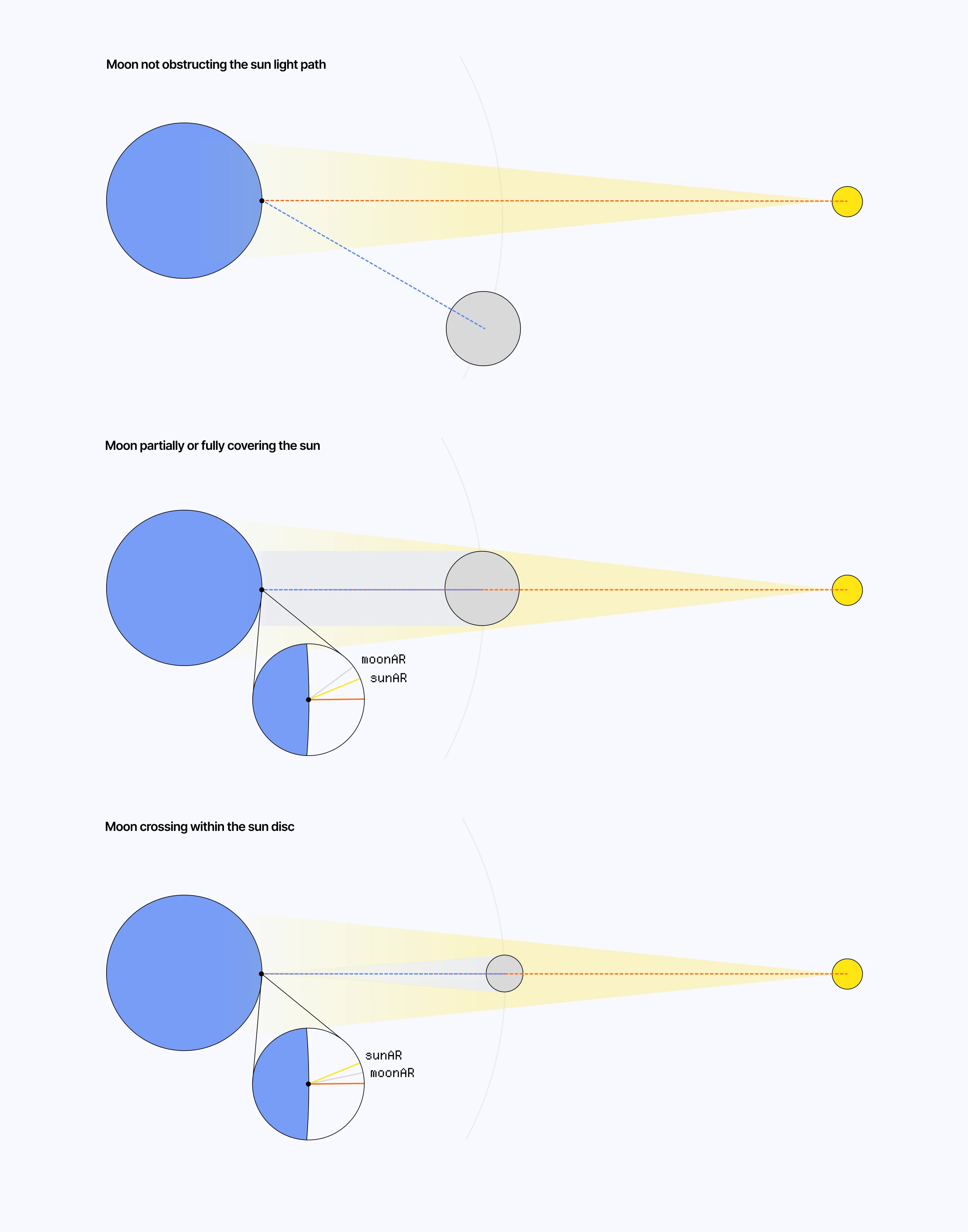
Diagram showcasing the different obstruction scenario handled by our sun visibility test 该图表展示了我们的太阳能可见度测试所涵盖的各种遮挡情况。
We need a function that can handle the three cases described in the diagram above:
我们需要一个能够处理上图中所描述的三种情况的函数:
- When the moon is not obstructing the sun.
当月亮没有遮住太阳的时候。 - When it is, but is larger or close to the size of the sun from the camera’s POV.
当它如此时,从相机的视角来看,它的大小会与太阳相当,或者至少接近太阳的大小。 - When it is, but fits within the radius of the sun from the camera’s POV.
当物体位于摄像机所处位置、且其距离在太阳的半径范围内时。
sunVisibility function sunVisibility 函数
float sunVisibility(vec3 point) {
  vec3 sunDir = normalize(sunDirection);
  vec3 toMoon = moonPosition - point;
  float moonDist = length(toMoon);
  vec3 moonDir = normalize(toMoon);

  if (moonDist <= 1e-5) {
    return 1.0;
  }

  // Compare the apparent positions and sizes of the sun and moon in the sky.
  float angularSep = acos(clamp(dot(sunDir, moonDir), -1.0, 1.0));
  float sunAngularRadius = SUN_RADIUS / SUN_DISTANCE;
  float moonAngularRadius = moonRadius / moonDist;
  float outerEdge = sunAngularRadius + moonAngularRadius;

  // No overlap between the sun and moon disks: full sunlight.
  if (dot(sunDir, moonDir) < 0.9) {
    return 1.0;
  }

  // The moon appears larger than the sun, so it can fully cover it near the center.
  if (moonAngularRadius >= sunAngularRadius) {
    float innerEdge = moonAngularRadius - sunAngularRadius;
    return max(0.075, smoothstep(innerEdge, outerEdge, angularSep));
  }

  float innerEdge = sunAngularRadius - moonAngularRadius;
  float minVisibility = clamp(
    1.0 - (moonAngularRadius * moonAngularRadius) / (sunAngularRadius * sunAngularRadius),
    0.0,
    1.0
  );

  // Partial overlap: smoothly fade between the minimum and full sunlight.
  return mix(minVisibility, 1.0, smoothstep(innerEdge, outerEdge, angularSep));
}
Here, float angularSep = acos(clamp(dot(sunDir, moonDir), -1.0, 1.0)) represents the angular separation between the sun and moon directions.
在这里, float angularSep = acos(clamp(dot(sunDir, moonDir), -1.0, 1.0)) 表示太阳和月亮之间的角距离。
dot(sunDir, moonDir)represents the alignment between both directions.
dot(sunDir, moonDir)代表了两个方向之间的对齐情况。acosconverts it back to an angle.
acos会将其再次转换为角度。
We can then use this value to compare it with the different angular thresholds outerEdge and innerEdge, representing, respectively, the angles at which the two discs start touching externally / internally.
我们可以利用这个数值来与不同的角度阈值 outerEdge 和 innerEdge 进行比较。这两个角度分别代表了两个圆盘开始在外侧/内侧接触时的角度。
The demo below implements this sunVisibility function on top of our previous example, and also adds a moon mesh to our system. Try to align the moon with the sun, and notice how our Atmospheric Scattering shader properly handles the lack of light in those cases.
下面的演示是在我们之前的示例基础上实现了该 sunVisibility 函数。同时,我们还向系统中添加了月亮模型。试着将月亮与太阳的位置对齐,然后观察一下“大气散射”着色器是如何妥善处理这些情况下的光线缺失问题的。
Outer-Worldly Atmosphere 异星大气
Another bonus section! It’s your lucky day! The model we’ve been using throughout this article to simulate atmospheric density and scattering is mostly governed by a handful of constants:
又有一个额外的奖励内容!今天真是你的幸运日!在本文中,我们用来模拟大气密度和散射现象的模型,其实主要取决于几个常数而已:
- The radius of the planet and atmosphere
这颗行星及其大气的半径 RayleighScaleHeightandRayleighBeta.RayleighScaleHeight和RayleighBeta。MieScaleHeight,MieBeta,mieBetaExt, andmieG
MieScaleHeight、MieBeta、mieBetaExt和mieGOzoneHeightandOzoneWidthOzoneHeight和OzoneWidth
These are the main knobs that make our rendered atmosphere look the way it does. Thus, by tweaking them to the right set of values, we could, in theory, approach a martian atmosphere or even other planets’. Below is the set of values I set for Mars:
这些参数是决定渲染出的大气效果的关键因素。因此,通过将它们调整到合适的数值,理论上我们就可以呈现出类似火星或其它行星的大气效果。以下是我为火星设定的参数值:
// These values are only approximative

const Mars = {
  planetRadius: 3390,
  atmosphereRadius: 3500, // ~110 km thick
  rayleighScaleHeight: 11.1,
  rayleighBeta: new THREE.Vector3(0.019, 0.013, 0.0057),
  mieScaleHeight: 1.5,
  mieBeta: 0.04,
  mieBetaExt: 0.044,
  mieG: 0.65,
  ozoneCenterHeight: 0.0,
  ozoneWidth: 1.0,
  ozoneBetaAbs: new THREE.Vector3(0.0, 0.0, 0.0),
  sunIntensity: 15.0,
  planetSurfaceColor: '#8B4513',
};
Just replacing our constants with these gives us a more dusty, orangy atmosphere. Even better, we get Mars’ distinctive blue hue at sunset! Below are a couple of screenshots I took while working on this. You can try plugging those values into the previous demo to see the result by yourself.
只要用这些数值来替换原来的常数,就能得到一种更加浑浊、呈橙色的大气效果。更妙的是,这样还能呈现出火星在日落时的独特蓝色色调!下面是我在处理这个任务时拍的一些截图。你可以试着将这些数值代入之前的演示程序中,亲自看看效果如何。
LUT Based Atmospheric Scattering基于 LUT 的大气散射模拟
The resulting shader we’ve built, albeit intuitive and able to render atmosphere at small and large scales, is unfortunately quite expensive to run:
我们所开发的着色器虽然使用起来很直观,而且能够处理各种规模的大气效果,但遗憾的是,其运行成本相当高。
- We have a large amount of
PRIMARY_STEPSin our raymarching loop.
在我们的 raymarching 循环中,使用了大量的PRIMARY_STEPS。 - We have a nested loop for lightmarching.
我们在 lightmarching 中使用了嵌套循环。 - We perform all the math at full screen resolution.
所有的数学计算都是在全屏分辨率下进行的。
Alongside tackling those drawbacks, I also wanted to study how the pros were doing it when I reached this point in my exploration of atmospheric scattering. Sebastian Hillaire proposed in his paper titled A Scalable and Production Ready Sky and Atmosphere Rendering Technique, a method to render atmosphere based on Look Up Tables (LUTs), i.e. textures that can hold expensive scattering calculations, so the final render samples and composes those precomputed textures.
在努力克服这些缺点的同时,我还想研究一下,当我在大气散射领域的研究达到这个阶段时,那些专家们是如何处理的。Sebastian Hillaire 在他的论文《一种可扩展且适用于实际应用的天空与大气渲染技术》中提出了一种基于查找表来渲染大气的方法。所谓查找表,其实就是能够存储复杂散射计算结果的纹理数据。最终,渲染结果就是由这些预先计算好的纹理构成的。
In this part, we will look into the respective implementations of:
在这一部分中,我们将分别探讨以下内容的实现方式:
- Transmittance LUT, which stores the amount of light that survives as it travels through the atmosphere.
透射率 LUT 用于存储光线在大气中传播过程中所保留下来的光量。 - Sky-view LUT, which stores the resulting sky color for a given camera position
天空视图 LUT:用于存储在特定摄像机位置下所对应的天空颜色。 - Aerial Perspective LUT, which stores the atmospheric haze/fog between the camera and visible scene geometries, including the amount of light added by scattering and its effect on the scene’s colors.
大气透视 LUT 用于存储相机与可见场景之间的大气雾气效果,包括因光线散射而产生的光线强度变化,以及这些变化对场景颜色的影响。
Transmittance LUT 透射率查找表
In our original shader, every sample point calls the lightmarch function to get the amount of light from our sun that reaches it, which, as you may guess, is quite expensive. The goal of this LUT is to store that data beforehand, preferably at a low resolution, so we can then load it into subsequent LUTs whenever we need that light data.
在我们的原始着色器中,每个采样点都需要调用 lightmarch 函数来获取照射到该点的太阳光强度。正如你所料,这种处理方式相当耗费计算资源。而这个 LUT 的作用就是预先存储这些数据,最好是以较低的分辨率来存储。这样,每当需要使用这些光照数据时,我们就可以直接从 LUT 中获取所需的数据了。
My implementation for this LUT, and any that follows, consists of:
我对这个 LUT 的实现方式,以及后续所有类似 LUT 的实现方式,都是如此:
- Define a dedicated Frame Buffer Object at a specific resolution. For this one in particular, I picked
250 x 64.
在特定的分辨率下,定义一个专用的帧缓冲区对象。对于这个例子,我选择了250 x 64作为该帧缓冲区对象的标识。 - Define a material with a custom shader that will hold the logic to generate our LUT data.
使用自定义着色器来定义一种材料,该着色器将负责生成所需的 LUT 数据。 - Apply it to a full-screen quad in a dedicated scene, in this case,
transmittanceLUTScene.
将其应用到某个专用场景中的全屏四边形上,也就是transmittanceLUTScene所在的位置。 - Render the scene, and pass the resulting texture as a uniform to downstream LUTs.
渲染场景后,将生成的纹理作为统一参数传递给后续的 LUT 处理过程。
It may seem a bit convoluted, but as said before, ideally, you’d use WebGPU and compute shaders for this and thus not need those FBOs.
这看起来可能有点复杂,但正如之前所说,理想情况下,应该使用 WebGPU 和计算着色器来实现这一功能,这样一来就无需再使用那些 FBO 了。
For the tramittance, we’re extracting the expensive lightmarch loop into its own pass by putting it in the transmittanceLUTFragmentShader. The code below is what I used to generate my texture:
对于透射率,我们将成本较高的 lightmarch 循环提取成单独的 pass,放入 transmittanceLUTFragmentShader 中。下面的代码就是我用来生成纹理的:
Transmittance LUT 透射率查找表
void main() {
  float mu = mix(-1.0, 1.0, vUv.x);

  float radius = mix(planetRadius, atmosphereRadius, vUv.y);
  vec3 rayOrigin = vec3(0.0, radius, 0.0);
  float sinTheta = sqrt(max(1.0 - mu * mu, 0.0));
  vec3 rayDir = normalize(vec3(sinTheta, mu, 0.0));

  vec2 atmosphereHit = raySphereIntersect(
    rayOrigin,
    rayDir,
    vec3(0.0),
    atmosphereRadius
  );

  vec2 planetHit = raySphereIntersect(
    rayOrigin,
    rayDir,
    vec3(0.0),
    planetRadius
  );

  float rayLength = atmosphereHit.y;

  if (rayLength <= 0.0) {
    gl_FragColor = vec4(1.0);
    return;
  }

  if (planetHit.x > 0.0) {
    gl_FragColor = vec4(0.0, 0.0, 0.0, 1.0);
    return;
  }

  float stepSize = rayLength / float(TRANSMITTANCE_STEPS);
  float rayleighOD = 0.0;
  float mieOD = 0.0;
  float ozoneOD = 0.0;

  for (int i = 0; i < TRANSMITTANCE_STEPS; i++) {
    float t = (float(i) + 0.5) * stepSize;
    vec3 samplePoint = rayOrigin + rayDir * t;
    rayleighOD += rayleighDensity(samplePoint) * stepSize;
    mieOD += mieDensity(samplePoint) * stepSize;
    ozoneOD += ozoneDensity(samplePoint) * stepSize;
  }

  vec3 tau =
    rayleighBeta * rayleighOD +
    mieBetaExt * mieOD +
    ozoneBetaAbs * ozoneOD;

  gl_FragColor = vec4(exp(-tau), 1.0);
}- For each pixel, we ray march from
vec3(0.0, radius, 0.0), which grows betweenplanetRadiusandatmosphereRadiusalong thevUv.ycoordinate.
对于每个像素,我们都从点vec3(0.0, radius, 0.0)开始进行 raymarching。该点沿着vUv.y坐标轴,在planetRadius和atmosphereRadius之间移动。 - The direction
rayDirdefines the light direction for any given pixel of our LUT, which varies betweenmu = -1, i.e., a downward direction toward the planet’s surface,rayDir = vec3(0.0, -1.0, 0.0), andmu = 1, a upward direction toward space,rayDir = vec3 (0.0, 1.0, 0.0). Whenmu = 0,rayDir = vec3(1.0, 0.0, 0.0)meaning the light travels horizonally, grazing the atmosphere.
方向rayDir决定了 LUT 中每个像素的光线方向。该方向可以是mu = -1,即朝向行星表面的向下方向;也可以是rayDir = vec3(0.0, -1.0, 0.0)和mu = 1,即朝向太空的向上方向;还有rayDir = vec3 (0.0, 1.0, 0.0)。当为mu = 0或rayDir = vec3(1.0, 0.0, 0.0)时,表示光线以水平方向传播,掠过大气层。 - We use the same
raySphereIntersectand atmospheric scattering functions introduced earlier.
我们继续使用之前提到的相同raySphereIntersect函数和大气散射函数。
This results in the following transmittance LUT texture:
这样就得到了如下的透射率 LUT 纹理:
Uniforms 参数
Here’s how you can interpret this texture:
你可以这样理解这种纹理:
- The x-axis represents the angle of the light. On the left side, we have light looking straight down towards the ground, hence the dark colors. The right side, on the other hand, represents light looking straight up.
- The y-axis represents the altitude. The bottom of the image is the ground / sea level, while the top is the edge of our atmosphere.
- Pure white represents a transmittance of 100% where light has a clear path.
- Black/colored areas represent the ground/the part where the air is at its thickest, especially near the ground where some of the light is extinct.
Subsequent LUTs can now answer the question of “how much light survives at a given angle and altitude through our atmosphere” very quickly by just looking up that value in this texture.
Sky View and Aerial Perspective LUTs 天空视图与大气透视 LUT
These two LUTs leverage the transmittance data we just computed in its respective texture and answer two complementary questions:
这两个 LUT 利用了我们刚刚计算出的各色纹理的透射率数据,从而回答了两个相互补充的问题:
- If I look in a specific direction from the ground up, what color is the sky? Sky Color
如果我从地面上朝某个特定方向望去,天空是什么颜色呢?天空的颜色究竟是什么? - How much atmosphere is between my current position and any object in the scene? Atmospheric Fog
我当前所在的位置与场景中的任何物体之间,有多少大气层呢?还有,还有大气雾气的影响。
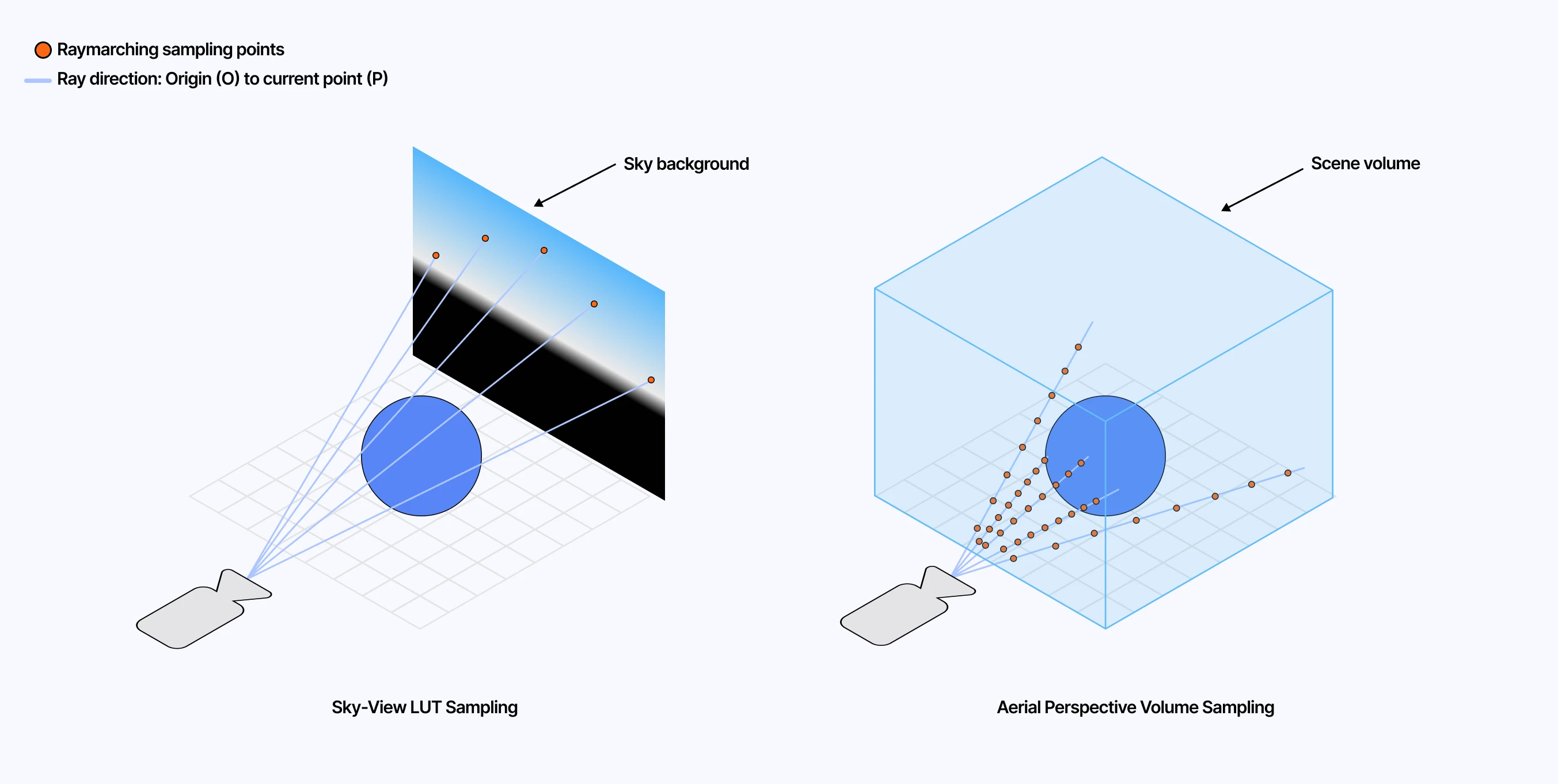
Diagram showcasing the sampling processes for our Sky-View and Aerial Perspective LUTs 该图表展示了我们在制作 Sky-View 和 Aerial Perspective LUT 时所采用的采样流程。
Combining both those LUTs will give us the full atmospheric scattering effect. The former handles far-field color while the latter calculates near-field haze. Using a similar process involving FBO and off-screen scenes, we can define distinct shaders to generate both LUTs.
将这两个 LUT 结合起来,就能实现完整的大气散射效果。前者负责处理远场颜色的处理,后者则负责计算近场的雾效。通过类似的处理方式,利用 FBO 和屏幕外场景,我们可以分别定义不同的着色器来生成这两个 LUT。
For the Sky View texture, I ended up with the following code:
对于“Sky View”纹理,我最终使用了以下代码来实现:
Excerpt of the Sky View LUT
“Sky View” LUT 的摘录/片段
vec3 getSkyViewForward(vec3 up) {
  // Project the sun direction onto the local horizon so azimuth has a stable reference.
  vec3 projectedSun = sunDirection - up * dot(sunDirection, up);
  return normalize(projectedSun);
}

vec3 getSkyViewRayDir(vec2 uv, vec3 up) {
  vec3 forward = getSkyViewForward(up);
  vec3 right = normalize(cross(forward, up));

  // Horizontal angle around the sky, centered around the projected sun direction.
  float azimuth = (uv.x * 2.0 - 1.0) * PI;

  // Quadratic mapping: uv.y still covers [-PI/2, PI/2],
  float elevation = (uv.y * uv.y - 0.5) * PI;

  float cosElevation = cos(elevation);
  vec3 horizontal = cos(azimuth) * forward + sin(azimuth) * right;

  return normalize(horizontal * cosElevation + up * sin(elevation));
}

void main() {
  vec3 rayOrigin = uCameraPosition;
  vec3 up = normalize(rayOrigin);
  vec3 rayDir = getSkyViewRayDir(vUv, up);
  vec3 planetCenter = vec3(0.0);

  vec2 atmosphereHit = raySphereIntersect(rayOrigin, rayDir, planetCenter, atmosphereRadius);
  vec2 planetHit = raySphereIntersect(rayOrigin, rayDir, planetCenter, planetRadius);

  // Skip rays that never enter the atmosphere.
  if (atmosphereHit.y <= 0.0) {
    gl_FragColor = vec4(0.0, 0.0, 0.0, 1.0);
    return;
  }

  // March only through the visible atmospheric segment, stopping early if the ray hits the planet.
  float atmosphereNear = max(atmosphereHit.x, 0.0);
  float atmosphereFar = atmosphereHit.y;
  if (planetHit.x > atmosphereNear) {
    atmosphereFar = min(atmosphereFar, planetHit.x);
  }

  float atmosphereSegmentLength = atmosphereFar - atmosphereNear;
  float stepSize = atmosphereSegmentLength / float(SKY_VIEW_STEPS);

  // Same atmospheric scattering loop as before, but this time along the
  // Sky View ray direction and using the Transmittance LUT for sunlight.

  // ...

  gl_FragColor = vec4(scatteredLight, 1.0);
}
The major thing to highlight here is the getSkyViewRayDir, which defines our raymarching ray directions. In this case:
这里需要重点注意的是 getSkyViewRayDir,它决定了 raymarching 时射线的传播方向。在本例中:
- The x-axis, vUv.x maps to the azimuth, i.e., left-to-right directions from
[-PI, PI].
x 轴上的 vUv.x 值对应的是方位角,也就是从[-PI, PI]点开始的左右方向。 - The y-axis,vUv.y, maps to the elevation, as a quadratic mapping
(vUv.y * vUv.y - 0.5) * PI3, i.e., our vertical sky angle ranging from[-PI/2, PI/2].
y 轴,即 vUv.y,表示高度值。该值是通过二次函数来确定的,即(vUv.y * vUv.y - 0.5) * PI3 。因此,我们的垂直天顶角范围为[-PI/2, PI/2]。 - Finally, we turn those two angles into a 3D
rayDir:uppoints toward the sky,forwardpoints along the horizon toward the sun, andrightlets us sweep left and right around the sky.
最后,我们将这两个角度转化为三维空间中的坐标:up指向天空,forward则沿着地平线指向太阳,而right则允许我们左右扫视天空。
With this definition of our rayDir, our raymarching loop here yields a texture representing the color of the sky for directions across the entire sky dome.
根据我们对 rayDir 的定义,这里的射线追踪算法能够生成出一种纹理,该纹理能够反映整个天穹各方向上的天空颜色。
When it comes to the Aerial Perspective, as mentioned earlier, I slightly diverged from Hillaire’s paper. My resulting texture is a 2D texture where each pixel corresponds to one visible screen pixel. I rely on the depth buffer of the scene to tell how far along the ray we should march and accumulate scattering.
关于“空气透视效果”的处理方式,如前所述,我稍微偏离了 Hillaire 的算法。我所创建的纹理是一种二维纹理,其中每个像素都对应屏幕上的一个可见像素。我利用场景的深度缓冲区来决定光线应传播多远,从而计算出相应的散射效果。
As a result, this lets me reuse more or less the same scattering code introduced in the first part, except that now each sample pulls sunlight visibility from the Transmittance LUT. The output stores the accumulated atmospheric scattering in RGB and a packed view transmittance value in alpha, which we will use later during composition.
这样一来,我就可以再次使用在第一部分中已经用到的散射计算代码了。只不过现在,每个采样点都是从“透射率 LUT”中获取与阳光相关的数值。输出结果以 RGB 格式存储了经过大气散射后的光线信息,而阿尔法通道则存储了透射率值。这些数据将在后续的图像合成过程中被用到。
Excerpt of the Aerial Perspective LUT
“空气透视”LUT 的摘录/片段
void main() {
  float depth = texture2D(depthBuffer, vUv).x;

  // Reconstruct the world-space position for this screen pixel from the depth buffer.
  vec3 rayOrigin = uCameraPosition;
  vec3 worldPosition = getWorldPosition(vUv, depth);
  vec3 rayDir = normalize(worldPosition - rayOrigin);
  float sceneDepth = logDepthToRayDistance(vUv, depth);

  vec2 atmosphereHit = raySphereIntersect(rayOrigin, rayDir, vec3(0.0), atmosphereRadius);
  vec2 planetHit = raySphereIntersect(rayOrigin, rayDir, vec3(0.0), planetRadius);

  if (atmosphereHit.y <= 0.0) {
    gl_FragColor = vec4(0.0, 0.0, 0.0, 1.0);
    return;
  }

  // March only through the visible part of the atmosphere:
  // stop at the scene depth, or earlier if the ray hits the planet.
  float atmosphereNear = max(atmosphereHit.x, 0.0);
  float atmosphereFar = atmosphereHit.y;

  if (planetHit.x > 0.0) {
    atmosphereFar = min(atmosphereFar, planetHit.x);

    if (sceneDepth < planetHit.x - 2.0) {
      atmosphereFar = min(atmosphereFar, sceneDepth);
    }
  } else {
    atmosphereFar = min(atmosphereFar, sceneDepth);
  }

  float segmentLength = atmosphereFar - atmosphereNear;
  float stepSize = segmentLength / float(AERIAL_PERSPECTIVE_STEPS);

  // Same scattering loop as before, but along the view ray for this pixel.
  for (int i = 0; i < AERIAL_PERSPECTIVE_STEPS; i++) {
    float t = atmosphereNear + (float(i) + 0.5) * stepSize;
    vec3 samplePoint = rayOrigin + rayDir * t;

    // Instead of raymarching toward the sun, look up sunlight visibility.
    vec3 sunTransmittance = sampleTransmittanceLUT(samplePoint, sunDirection);

    // Accumulate Rayleigh and Mie scattering using sunTransmittance.
    // ...
  }

  // RGB stores scattered light; alpha stores view transmittance for composition.
  gl_FragColor = vec4(scatteredLight, packedTransmittance);
}
Composition 构成/组成
With the Sky-view and Aerial Perspective LUTs generated, we have only one step remaining: combining them in a final post-processing pass to achieve the full LUT-based atmospheric scattering result. The code mainly consists of:
在生成了天空视图和空中视角的 LUT 之后,我们只需再执行最后一步操作:将它们结合起来,从而得到基于 LUT 的完整大气散射效果。该代码主要由以下部分组成:
- Converting the current rayDir into skyViewUV coordinates, so given any direction in the sky, we know where to sample the precomputed Sky-view LUT.
将当前的 rayDir 转换为 skyViewUV 坐标,这样,无论天空中的方向如何,我们都能知道该在何处采样预先计算好的 Sky-view LUT。
vec2 getSkyViewLUTUv(vec3 rayDir, vec3 planetCenter) {
  vec3 up = normalize(uCameraPosition - planetCenter);
  vec3 forward = getSkyViewForward(up);
  vec3 right = normalize(cross(forward, up));

  float vertical = clamp(dot(rayDir, up), -1.0, 1.0);
  vec3 horizontal = rayDir - up * vertical;

  // Convert the 3D ray direction back into the same azimuth/elevation
  // coordinates used when generating the Sky View LUT.
  float azimuth = atan(dot(horizontal, right), dot(horizontal, forward));
  float elevation = asin(vertical);
  float elevation01 = clamp(elevation / PI + 0.5, 0.0, 1.0);

  return vec2(
    azimuth / (2.0 * PI) + 0.5,
    sqrt(elevation01)
  );
}

vec3 sampleSkyViewLUT(vec3 rayDir, vec3 planetCenter) {
  vec2 uv = getSkyViewLUTUv(rayDir, planetCenter);
  return texture2D(skyViewLUT, uv).rgb;
}- Reconstructing the view ray from the depth buffer and checking whether that ray hits the planet.
从深度缓冲区中重建视线,然后判断该视线是否与行星相交。 - Applying the Aerial Perspective LUT to scene geometry, using its alpha channel as view transmittance and its RGB channels as scattered light.
将 Aerial Perspective LUT 应用于场景中的几何体:利用其 Alpha 通道来表示视线透射率,用 RGB 通道来表示散射光。 - Sampling the Sky View LUT for background pixels.
正在为背景像素采样“Sky View”LUT。
void mainImage(const in vec4 inputColor, const in vec2 uv, out vec4 outputColor) {
  float depth = readDepth(depthBuffer, uv);
  vec3 rayOrigin = uCameraPosition;
  vec3 rayDir = normalize(getWorldPosition(uv, depth) - rayOrigin);
  vec3 planetCenter = vec3(0.0);
  vec2 planetHit = raySphereIntersect(rayOrigin, rayDir, planetCenter, planetRadius);
  vec3 color = inputColor.rgb;

  bool isBackground = depth >= 1.0 - 1e-7;

  // For scene geometry, blend the original color with the atmospheric haze.
  if (aerialPerspectiveEnabled && !isBackground) {
    vec4 aerialPerspective = sampleAerialPerspectiveLUT(uv);
    color = color * aerialPerspective.a + aerialPerspective.rgb;
  }

  // For background pixels, replace the empty background with the sky color.
  if (skyViewEnabled && isBackground) {
    color = inputColor.rgb + sampleSkyViewLUT(rayDir, planetCenter);
  }

  color = ACESFilm(color);
  color = pow(color, vec3(1.0 / 2.2));

  outputColor = vec4(color, 1.0);
}
The playground below contains all the full implementation of our LUT-based atmosphere: all the LUTs and their corresponding shader, as well as the final post-processing pass. It is a bit dense, so I’d recommend checking the implementation directly at this Github link, where you’ll find the code that renders the scene below.
下方的演示场景完整地展示了我们基于 LUT 的技术实现:所有的 LUT 数据、相应的着色器代码,以及最后的后期处理流程。由于内容较为复杂,我建议直接通过这个 Github 链接来查看相关代码。在该链接中,你可以找到用于渲染下方场景的完整代码。
Final Thoughts 最后思考
This version of atmospheric scattering may look almost identical to the one we worked on in the earlier parts of this post, but the underlying process is different: we split the work into smaller LUTs that we then compose in the final effect. Most importantly, instead of repeatedly raymarching toward the sun to figure out how much light reaches each sample, we can fetch that lighting information directly from the Transmittance LUT, replacing a costly nested loop with a simple texture lookup and resulting in a non-negligible performance boost for the final scene.
这种大气散射的实现方式,看起来与我们在这篇帖子前面部分所介绍的方案几乎相同。但实际上,其背后的处理机制有所不同:我们将整个处理过程拆分成多个较小的 LUT,然后再将它们组合起来以生成最终的效果。最重要的是,我们可以直接从透射率 LUT 中获取这些光照信息,用简单的纹理查找替代原本昂贵的嵌套 raymarching,从而显著提升最终场景的性能。
Despite that, my LUT-based implementation pales in comparison to what Sébastian Hillaire and others in the field came up with:
尽管如此,我基于 LUT 的实现方式,与塞巴斯蒂安·希莱尔以及该领域的其他人的成果相比,还是相形见绌。
- There’s some banding and flickering happening, particularly in the sky-view
画面中有一些条纹和闪烁现象,尤其是在天空部分的画面中更为明显。 - The shortcuts I took made the process less optimal than it could have been.
我所采取的捷径使得整个流程的效率大打折扣,没有达到应有的最佳效果。 - I should probably have used WebGPU from the get-go.
或许,我一开始就应该使用 WebGPU 的。
If you want to look at a real production-grade implementation, I highly recommend checking out three-geospatial by Shoda Matsuda (@shotamatsuda). His work on skies, clouds, and geospatial rendering has been a huge reference point for me, and the images he shares on social media speak for themselves.
如果你想了解真正符合生产级标准的实现方式,我强烈推荐你去看看 Shoda Matsuda(@shotamatsuda)开发的 three-geospatial 项目。他在天空、云层和地理空间渲染方面的研究成果对我来说极具参考价值。他在社交媒体上分享的图片也足以证明其技术的卓越性。
Nonetheless, I learned a lot throughout this entire project, especially through the LUT-based approach, which took me out of my comfort zone when it comes to creating screen-space depth-aware post-processing effects. It also consolidated some previous learnings, and resulted in a series of beautiful visuals (which is the most important after all).
不过,通过整个项目的实施,我学到了很多东西。尤其是通过基于 LUT 的方法,我突破了自己在创建具有深度感知效果的后期处理效果方面的舒适区。这一方法还帮助我巩固了之前学到的知识。最终,我们打造出了一系列精美的视觉效果——这才是最重要的。
I’m very happy with the result of those experiments. I also worked on adding volumetric clouds on top of that, but the result is still a bit of a mixed bag and needs more work put into it before I could be proud enough of it to showcase it in a write-up. This will have to wait. Until then, I’m looking forward to leveraging that work to complement my upcoming projects and scenes I have been slowly shaping in my head.
我对那些实验的结果非常满意。我还尝试在模型上添加了具有立体感的云层效果,不过效果还有待改进。在能够满意地将其展示出来之前,还需要进一步改进。不过,我期待着能利用这些成果来完善我正在构思中的各种项目和场景。
- 4
I have tried this many times over.
我已经尝试了很多次了。 - 5
Real-time Cloudscapes with Volumetric Raymarching introduces a lot of concepts used here.
《基于体积 raymarching 的实时云景渲染》介绍了许多在此技术中使用的概念。 - 6
This is a workaround to avoid too much blinking of the skyview at a large distance
这是一种避免在远距离视角下天空画面闪烁过度的解决方法。
For a more true to life implementation, we must treat the sky and its color as the result of light interacting with air and its constituents, while taking into account several variables, such the altitude of the observer, the amount of dust, the time of day, etc, all of that in a volume.
为了更真实地再现这一现象,我们必须将天空及其颜色视为光线与空气及其中各种成分相互作用的结果。同时,还需要考虑多种因素,比如观察者所处的海拔高度、空气中的尘埃含量、一天中的不同时间等等。所有这些因素都需在特定的空间范围内加以考虑。
With that established, our goal for this first part is to use this as guiding principle to lay the foundation for our atmosphere shader, and get to a result that feels almost indistinguishable from a real sky, at any time of the day.
既然如此,本阶段的目标就是以这一原则作为指导,为大气着色器的开发奠定基础。最终要实现的效果是:无论是一天的中的什么时间,渲染出来的大气效果都应与真实的天空几乎无法区分。
Computing transmittance 计算透射率
//...

float dR = rayleighDensity(h);
viewOpticalDepth += dR * stepSize;

vec3 transmittance = exp(-rayleighBeta * viewOpticalDepth);
scattering += dR * transmittance * stepSize;

//...
With this in place, we can now describe how light is attenuated as it travels through the atmosphere. However, density and transmittance only tell us how much light is available to scatter, not how that light is distributed toward the viewer. For that, we need to account for the angle between the incoming sunlight and the view ray, which is what the Rayleigh phase function models.
有了这些知识,我们现在就可以描述光在穿过大气层时是如何被衰减的。不过,密度和透射率只能告诉我们有多少光可以被散射,而无法说明这些光是如何向观察者方向传播的。为此,我们需要考虑入射阳光与观察方向之间的夹角,而这正是瑞利相位函数所用来描述的。
Rayleigh phase function 瑞利相位函数
//...

// We consider the sun constant at its zenith here
const vec3 SUN_DIRECTION = normalize(vec3(0.0, 1.0, 1.0));

float rayleighPhase(float mu) {
  return 3.0 / (16.0 * PI) * (1.0 + mu * mu);
}

//...
void main() {
  //...
  float phase = rayleighPhase(dot(skyDir, SUN_DIRECTION));

  // Raymarching loop

  scattering *= SUN_INTENSITY * phase * rayleighBeta;

  float horizon = smoothstep(-0.12, 0.05, skyDir.y);
  vec3 color = mix(SPACE_COLOR, scattering, horizon);
  color = ACESFilm(color);

  fragColor = vec4(color, 1.0);
}
Putting all this together, we can have a somewhat accurate representation of how much scattered light accumulates along a given ray at any given altitude. The widget below represents the process we just described, showing you:
把这些部分组合起来,我们就能近似计算:在任意高度上,沿着某条特定射线路径,会有多少散射光被累积下来。下方的图表展示了我们刚才所描述的过程。
- The sample steps along a single ray
样本沿着单一光线移动的步骤/样本在单一光线路径上的移动过程 - The resulting pixel color obtained from this process (an approximation)
通过这一过程得到的像素颜色值(仅为近似值)
20
3.5 km 3.5 公里
As you can see, we’re accumulating shades of blue at lower altitude! This is mostly due to the Rayleigh scattering coefficient’s value:
如您所见,我们在较低海拔地区观察到了越来越多的蓝色色调!这主要得益于瑞利散射系数的作用。
- Red scatters very little 红色几乎不会扩散。
- Green a bit more 绿色散射稍多一些
- Blue the most 蓝色散射最多
Since shorter wavelengths scatter more strongly, more blue light is redirected toward the viewer, thus resulting in the sky appearing blue during daytime.
由于波长较短的光更容易发生散射,因此更多的蓝光会被重新定向到观察者的方向。这就是为什么在白天,天空会呈现蓝色的原因。
If we expand this idea into a full-on fragment shader, going from a single ray to one ray per pixel, we can render a realistic sky, as demonstrated below:
如果我们把这个想法进一步应用到完整的片段着色器中,也就是让每个像素都对应一条光线,那么我们就能渲染出逼真的天空效果,如下图所示:
Uniforms 参数
20.00
2.00
This raymarching process yields a beautiful blue sky, with a lighter white haze towards the horizon as rays travel through more atmosphere there, and deeper, darker blue colors as the altitude increases and the atmosphere gets thinner.
通过这种 raymarching 处理,我们可以得到美丽的蓝天效果:随着光线穿过更多的大气层,地平线处呈现出更浅的白色雾霭;而随着高度的增加,大气层变薄,颜色则变为更深的蓝色。
I have tried this many times over.
我已经尝试了很多次了。
Real-time Cloudscapes with Volumetric Raymarching introduces a lot of concepts used here.
《基于体积 raymarching 的实时云景渲染》介绍了许多在此技术中使用的概念。
This is a workaround to avoid too much blinking of the skyview at a large distance
这是一种避免在远距离视角下天空画面闪烁过度的解决方法。
Footnotes
-
You may have, at some point or another, tried to slap a blue gradient background behind some of your work in an attempt to give it a more “atmospheric” look and call it a day, but quickly noticed doing so never feels quite right .
你可能在某个时候尝试过,为自己的作品添加蓝色的渐变背景,希望能让作品看起来更“有氛围感”。但很快你就会发现,这样做其实并不理想 。 ↩ -
If you’ve read my article on volumetric clouds , we’re using a formula that may look familiar for this: Beer’s Law:
如果您读过我关于体积云的文章 ,那么您应该对这里所使用的公式并不陌生:比尔定律。 ↩ -
The y-axis,vUv.y, maps to the elevation, as a quadratic mapping
(vUv.y * vUv.y - 0.5) * PI, i.e., our vertical sky angle ranging from[-PI/2, PI/2].
y 轴,即 vUv.y,表示高度值。该值是通过二次函数来确定的,即(vUv.y * vUv.y - 0.5) * PI。因此,我们的垂直天顶角范围为[-PI/2, PI/2]。 ↩